Rocket
engines are a testament to engineering marvels, propelling humans and
satellites into space. It takes a lot of energy to put a rocket into space. Due
to this, scientists and engineers are always trying to find ways to reduce the
weight of rockets. The fuel itself is very heavy, which accounts for 90 – 95%
of the entire rocket’s weight, so to save weight on fuel, the only option is to
make rocket engines very efficient.
PULSE DETONATION ENGINE
This engine
was developed by Air Force Research Laboratory and Innovative Scientific
Solutions, Inc. It consists of 4 tubes that produce 200 pounds of thrust. But
how is a Pulse Detonation Engine different from conventional aircraft/rocket
engines?
To
understand that we first have to understand what detonation means. Conventional
jet and rocket engine works by igniting the fuel-air mixture with the help of
an igniter. If the speed of the flame front after combustion is below the speed
of sound (< Mach 1), then the combustion is called Deflagration.
If the speed of the flame front is more than the speed of sound (> Mach 1),
then the combustion is called Detonation.
Almost all combustion
engines work with Deflagration and pulse detonation and rotating detonation
engines, as their name implies, work on Detonation. Because combustion in
detonation engines is happening at such high speed these engines produce more
thrust for a given volume.
The video below shows a simple pulse detonation engine consisting of two valves and a spark plug. Air and fuel will enter through the valves which then burn with the help of a spark plug. Initially, the combustion will occur as deflagration but as it progresses down the tube it becomes a detonation. In the engine tested by Air Force Research Laboratory and Innovative Scientific Solutions, Inc. these pulses of detonation will occur 20 times per second in a single tube, and since the engine has 4 tubes it produces 80 pulses per second.
ROTATING DETONATION ENGINE
The problem
with pulse detonation engines is that they don’t produce thrust continuously,
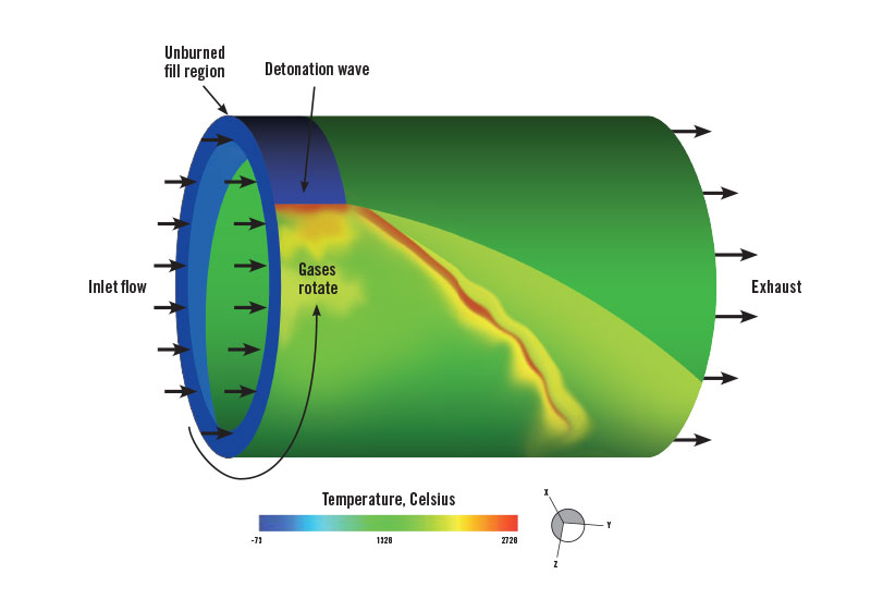
this problem is solved by Rotating Detonation Engine (RDE). These engines use
an annular combustion
chamber. The fuel is fed into the tube and then ignited with an igniter plug,
detonation begins and the shock wave starts traveling around the circumference
of the combustion chamber.
This shock wave increases the temperature and pressure of the gas behind it which then expands and exits the nozzle with extremely high velocity creating thrust. This solves the problem of creating detonation several times per second as the shock wave ignites the fuel-air mixture and due to its spiral nature, it produces continuous thrust.
Let’s now compare the combustion cycle of an RDE (Humphrey Cycle) and a normal Gas Turbine Engine (GTE) (Brayton Cycle) to understand the power output of an RDE.
 |
| Image credit: Real Engineering [YouTube] |
Here we can see that in the Brayton Cycle air enters from inlet [1-2]. After that, the compressor does work on air and increases the pressure [2-3]. Air enters the combustion chamber, where it expands rapidly keeping the pressure constant [3-4]. After combustion it enters the turbine stage where it further expands and its pressure drops. The area under these points represents the energy output of a GTE.
In RDE, the detonation wave increases the pressure instantaneously [3-4’], spiking it much higher than GTE. The area under the Humphrey Cycle is much larger than the area under the Brayton Cycle which indicates more energy output in RDE.
CHALLENGES
One of the main challenges of developing a rotating detonation engine is that the detonations are very hard to control and very unstable in nature.
Also, it is challenging to study the detonation inside the engine. Recent development in Computational Fluid Dynamics makes it possible to study it more precisely and develop methods to dampen instability inside an RDE.
Another challenge is developing material that can harness the immense energy that RDE produces because a detonation engine is of no use if it destroys our engine. To overcome this challenge NASA has developed a new metallic 3-D printing alloy called GRCCop-42 Copper made up of Copper, Chromium, and Niobium. Which have a very high melting point and high thermal conductivity. It can handle the high temperatures produced in RDE and due to its high thermal conductivity, it can dissipate the heat easily. And with the help of 3-D printing, it became possible to create incredibly complex geometry.
Injectors also have to be designed not only to handle a wide range of pressure and temperature but also rapid changes of pressure and temperature in this range.
These injectors are designed such that they allow fuel to pass with low resistance in one direction while resisting the backflow of fuel due to shock waves.
Conventional rocket nozzle design is also not suitable for the RDE as flow separation could occur which will decrease the engine efficiency.
Due to this Aerospike Nozzle is used in RDE, which solves the flow separation problem. And because it also requires an annular combustion chamber it is a perfect choice for RDE.
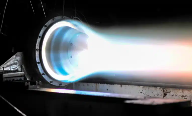
NASA successfully conducted tests of the Rotating Detonation Engine which shows that the special alloy can withstand the test, with the longest test being conducted for about 10 min.
If the reader is interested to know more about the rotating detonation engine I have given some links below:
- https://youtu.be/RVxgyz_avQM?si=mYqDFauNZtwsXHCx
- https://youtu.be/rG_Eh0J_4_s?si=-WA1s8zvM8f6dfpG
- https://www.intechopen.com/chapters/70511
- https://www.sciencedirect.com/science/article/abs/pii/S0360128518301783
- https://aerospaceamerica.aiaa.org/departments/increasing-engine-efficiency/
- https://innssi.com/pulsed-detonation-engine/


